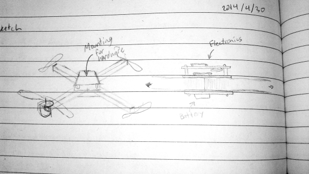
For the chassis I am envisioning cross bars of aluminium square tube braced by 2 or more thin plates which would also be the mounting points for the electronics and battery.
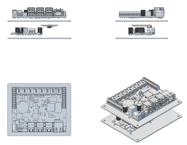
A few measurements later and I was able to make a model of the plates in some CAD software.
What is the world coming to when we can’t even build our own robots? Alas, I don’t trust my hands enough to drill the holes where they need to be (or fill in whatever excuse you want that lets me use a sweet CNC mill). The same CAD software used for the design will generate the G-code which will tell the mill where to put the holes. The G-code will look something like this:
N10 G20
N20 G0 G17 G40 G49 G80 G90
N30 G64
N40 (Standard Drill )
N50 T11 M6
N60 G43
N70 S20000 M3
N80 G00 Z0.3125
N90 X4.3307 Y0.1968
N100 G81 X4.3307 Y0.1968 Z-0.4375 R0.1625 F10.0
N110 G80
N120 G00 Z0.3125
N130 G81 X4.0488 Y1.3001 Z-0.4375 R0.1625 F10.0
The mill reads these codes in and moves the work piece around the cutting head based on the X-Y coordinates and moves the head up and down based on the Z coordinates given. You zero the head at the beginning and then the coordinates are all relative to that 0 point. For example: N100 G81 X4.3307 Y0.1968 Z-0.4375 R0.1625 F10.0 would be 4.3307 inches on X, 0.1968 inches on Y and -0.4375 inches on Z. The other parameters tell the mill things about bit speed and feed rate etc… but that’s beyond the scope of this post.
Who doesn’t love video? Here’s what it looks like:
After the milling was complete, I cut the plate out of the larger panel with a jig saw rather than using the mill on the recommendation of someone who does more machining than I do. The first prototype looks something like this:
What have I learned from this first pass?
- In hind sight, I should have used a plasma cutter instead of the jig saw (or at least used a less aggressive blade than I did) as the cut isn’t very clean. I could perhaps go over it with the mill to clean it up after the fact. The jig saw also warped the plate a bit since the blade was so aggressive. The plasma cutter wouldn’t have this problem.
- My zeroing wasn’t super awesome. The right hand holes are too close to the edge of the plate, it would probably be more effective to zero further towards the centre of the plate and then just cut away the excess material so that doesn’t happen.
- The hardest problem with milling seems to be securely attaching the work piece to the mill table. I don’t think I had the plate attached well enough and I was punished for it with some slightly wobbly cuts. I need a better way to lock it down before I go for prototype #2.
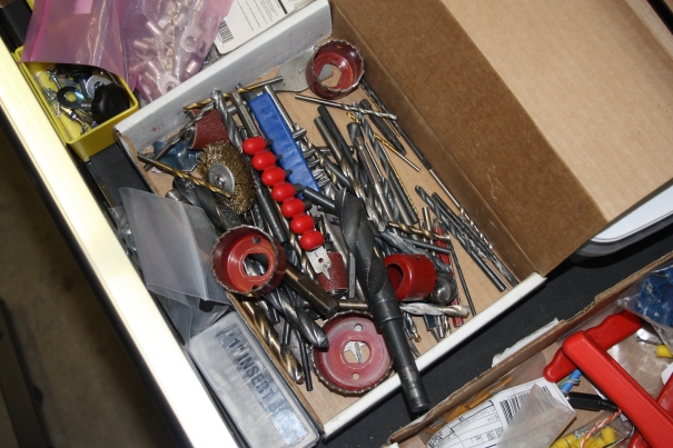
- Organization is important, otherwise your tool chest looks like this and it takes 20 minutes to find the right bit…
Check out the last post about the parts chosen for the quadcopter.


[…] up, designing and machining the chassis. Read the previous post about the quadcopter and the next post about machining the […]