Small voltages and currents pose difficulties when being measured, but solutions for measuring these tiny values do exist. You can use devices like the 1048 and 1051 Phidgets Temperature Sensors and 1046 Phidgets Bridge to read any small voltage. Here’s a quick explanation of how to set up these Phidgets and get them working to measure your small voltages and currents.
The Problems with Measuring Small Voltages and Currents

Various transducers for measuring current, power and voltage.
What if you want to measure voltages in the microvolts to tens of millivolts range? There are two problems with measuring a small voltage of this size. First, specialized amplification circuitry is necessary. The analog input on your PhidgetInterfaceKit or the ADC of your Arduino is totally unsuited for this task. Second, grounding is a problem. The circuit that’s doing the measuring of the voltages will have a ground, probably the ground of the PC that it’s plugged into. The circuit you’re measuring the voltage of will have its own ground. If these grounds are always less than a couple volts different, amplifiers can be designed that will work, but these are precise designs that need a high common mode rejection ratio (CMRR), something that isn’t practical for everybody.
At Phidgets, our solution for getting around these aforementioned problems is to make the grounds exactly the same. This is only possible with isolation, which means making the ground of your measuring circuit “float” with the ground of the circuit that you’re measuring. This is what the 3060 USB Isolator does, and you will need it if you plan on using a device like the temperature sensor or bridge to measure voltage or current.
A lot of current sensors (like the Phidgets 3584-3589 DC Current Transducers) work by measuring the magnetic field created by current. Small currents create such a tiny magnetic field that these sensors won’t measure correctly. At most, these current sensors that employ the magnetic field technique have a resolution of merely 10mA.
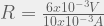
Instead of measuring a tiny magnetic field, we can measure the voltage drop over a small value resistor and calculate the current from that voltage measurement. This resistor will distort the circuit somewhat, so you want to use the smallest value possible. The resulting voltage will be tiny, but still measurable. Once you’ve got that measurement, just use Ohm’s law with your known resistance value to calculate the current:

Measuring Small Currents with DC Current Sensors

The 3511 DC current sensor and sensor adapter being used to measure a small current.
The 3511 DC Current Sensor (0-10mA), 3512 DC Current Sensor (1-100mA), and 3513 DC Current Sensor (0-1A) will work in certain situations. They come with internal 50Ω, 5Ω and 0.5Ω resistors, respectively. This might be too much resistance for what you’re trying to measure, resulting in too significant of a voltage drop for your system, and consuming too much power. If you find these resistances are unsuitable for your measurements, you’ll need to explore some of the other options described below.
On the plus side, these sensors are easy to connect to an 1144 12V Sensor Adapter and Phidget Interface Kit, meaning you can connect other Phidgets sensors, digital inputs and digital outputs with ease.
The values you obtain will have a 12-bit resolution. This isn’t terrible, but if you need to detect really minute changes, or need extreme precision, using one of the other options below will better meet your needs.
Measuring Small Currents with Temperature Sensors
The 1048 Phidget Temperature Sensor (4-input) and 1051 Phidget Temperature Sensor (1-input) are built for measuring thermocouples – but are really just precise voltmeters. They have a resolution of 16-bits and 12-bits, respectively.
To use the temperature sensor as a voltmeter, first connect the sensor to a USB isolator, then connect the inputs of the temperature sensor across a resistor. To choose the best resistor, you’ll need to decide what the maximum current you want to measure is. Once you have an idea of what the maximum amount of current that you will be measuring is, you can calculate the resistance you’ll need. The maximum voltage you can measure with a temperature sensor is ±6mV (when going both ways) or from -6mV to 50mV when going one direction. Allowing yourself to measure the full range of voltages will give you maximum resolution when calculating the current. However, the trade-off is that you’ll be using a larger resistor in the circuit you’re measuring, and that will distort your circuit more, so choose your voltage appropriately. Use Ohm’s law to calculate the required resistance:

For instance, if you’re looking to measure a current that might get up to ±10mA, and want maximum resolution:
You’ll need a 0.6Ω resistor.
Here, we want to measure the current going from a solar cell to a rechargeable battery. We connect a potentiometer set at 0.5Ω of resistance into the circuit between the solar cell and the battery. Then, we measure on either side of the resistor through a 1048 temperature sensor connected to a USB isolator. At the very start, when the solar panel was turned over, there is practically no voltage drop across the resistor, but when exposed to bright, natural light, the sensor reads a peak of 9.5mV. We can use the known resistance of 0.5Ω to calculate the current:

and the power:

 Schematic diagram for measuring the current between solar cell and battery with a Phidgets temperature sensor |
 Setup for measuring the current going between a solar cell and a battery with a Phidgets temperature sensor |
 Current between the solar cell and battery over 3 minutes |
|
When collecting the data with the Phidgets API, don’t forget to use the get potential function to obtain the millivolts measurement.
Measuring Small Currents with the Phidgets Bridge

How to connect 1kohm resistors when reading voltage.
For really small and precise measurements, the 1046 Phidgets Bridge can be used with the USB Isolator. Measuring with the bridge will produce errors if the supply voltage changes, but the USB isolator will keep the voltage quite steady.
Set up is similar to that for the temperature sensors, except that there are an extra two inputs on the bridge. Use two identical resistors (we sell 1KΩ 0.1% resistors) to tie the two wire leads (connected to either end of the current sensing resistor) to the +5V and ground (G) terminals, and then connect the other two terminals across the resistor where you’ll be measuring voltage.
The real advantage of using the Phidgets Bridge is the high precision it offers. You can get 24-bit resolution here (that’s at least 4000 times more precise than the DC current sensor mentioned first) and measurements down to nanovolts are easily doable.
When you begin collecting data, use the get BridgeValue function, which returns the value in mV/V. To convert this to millivolts, multiply by the voltage being supplied by the board, typically 5 volts. If you have a multimeter, you can measure this voltage precisely and multiply by that value, or do calibration on the readings by using your multimeter to take the voltage across the resistor and compare that to the value the bridge is reading.
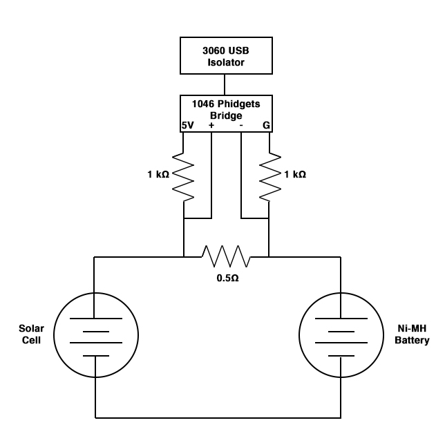 Schematic diagram for measuring the current between solar cell and battery with a Phidgets bridge |
 Setup for measuring the current going between a solar cell and a battery with a Phidgets bridge |
Now you know how to set up the 1046 Phidgets Bridge and the Phidget Temperature Sensors to measure voltage, and from there, current. The key to accurate measurements is choosing the right resistor for the system, as described above. If your resister is too small, you risk it heating up as you pass an excess of current through it, which will skew your measurements. If the resistor is too large, it may drain too much power from the system. But, once you have the right resistor, it’s fairly easy to get precise measurements of small voltages, like in our example of the solar cell and rechargeable battery. The advantage is more precision, and perhaps being able to repurpose Phidgets you’re not using anymore.
Have you had success with another method? Let us know in the comments how you measure small currents.
I'm an everyday walker, a passionate learner, and en educator creating experiences that grow eco and digital literacy. I'm living with stage IV colorectal cancer and type 1 diabetes, hoping to eek out as much life as possible before the cruel world takes me.

Hi! I want to measure Diode current with Arduino. The voltage range of measurement is from 0V to 5V and current changes from 1nA to 1mA. Which one is the proper system?