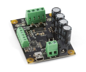
 By far the most frequently replaced board in Phidgets history has been the 1063 PhidgetStepper Bipolar controller.
Was it a bad Phidget? No, but motor controllers are often put on the front lines of a project, sandwiched between high voltage power supplies and high torque motors. I’d like to take a brief look at the most common ways a motor controller dies, and what countermeasures can be made (and have already been made) in order to protect your Phidget in these high-power applications.
Ground Loops
Whenever you have more than one circuit connected to the same ground, there is a possibility that one circuit will interfere with the other. A motor controller Phidget can be thought of as two different circuits: One circuit sends and receives data over USB, and is powered by USB. The other circuit deals with controlling the motor, and is powered by an external power supply. Since these two circuits need to communicate, they are connected electrically.

Since the motor controller’s power supply doesn’t connect to the earth ground, this situation is fine; each device has a separate ground. But suppose we had a slightly different situation, where a 1019 Phidget InterfaceKit is being used as a USB hub in between the computer and the motor controller:

In this diagram, both the motor controller and the InterfaceKit share a power supply. Normally, you’d expect current to flow from power to ground separately in each circuit, as indicated by the blue arrows. But since the ground is shared, there is an additional path for current to travel; up through the motor controller, across the USB cable, and down through the ground of the 1019’s power supply (the red arrow). When the board is first plugged in, it pulls a large amount of current to charge the capacitors. The motor control side of the Phidget is designed to handle this current, but the USB side and the 1019 are not. This ground loop can cause these high currents to blast through the USB circuit and the 1019, potentially destroying the circuits on either board.
Prevention
Luckily, ground loops can be easily prevented once you understand when they occur. The simplest way to prevent ground loops is to take care when designing your system, making sure that all interconnected components are grounded separately. If you absolutely must have multiple devices connected to the same ground, like in the previous example, you can add isolation to the system. The 3060 – USB Isolator is a product we sell for this exact situation. It uses a transformer to isolate power lines and opto-isolators for the data lines. Since current can’t cross this gap, the ground loop is broken and the USB side of your circuit is safe. Our new stepper controller, the 1067 – PhidgetStepper HC, fixes this problem by having isolation built-in to the board.
Another solution is to reduce the resistance of the favourable paths by using short, thick wire. Electricity takes the path of least resistance and these currents are no different. You won’t eliminate the ground loop with this method, but you may reduce the current going through the wrong path to the point where it doesn’t affect your system. This is the method we used with the four DC motor controllers in our MURVV project.
Overheating
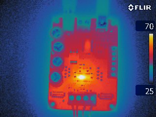
An infra-red thermal image of the 1063 stepper controller in operation. Can you spot the driver chip?
The chip that controls the motor has a tough job; it has to switch the direction of the motor current in each of the coils thousands of times per second. This switching is done with transistors, which have high resistance when closed. Where there’s resistance, there’s heat.
When you push the limits of a motor controller’s capability for an extended period of time, the driver chip could overheat and eventually fail.
Prevention
To prevent overheating from occurring, you should know the limits of your motor controller and try to run it below the maximum that it’s rated for, to give your project a bit of breathing room. For example, if you connect or disconnect motor wires while the motor is powered and engaged, it can cause some minor sparking to occur between the wires and the terminals. Under normal circumstances this probably won’t harm the Phidget, but if you’re already running at the absolute maximum, it could be the straw that breaks the camel’s back. Running below the maximum rating means that minor issues like these won’t become major issues.
If you need to run at the maximum specifications of a motor controller, you can always deal with heat by putting a heatsink and/or cooling fan on the board. While we don’t currently sell heatsinks or fans designed for our motor controllers, some of our more industrious customers have made custom enclosures with heatsinks and fans. In the case of the 1067, the controller has a rugged enough design that it can put up with the maximum specifications we’ve rated it for, no problem.
Current Spikes (Back EMF)
You may remember from science class that a motor can be used as a generator if you connect it to a circuit and turn the shaft. Take a DC motor for example:

As you can see, clockwise rotation of the motor results in a different direction of current flow depending on whether it’s acting as a generator or a motor. What may not be immediately obvious is that whenever you drive a motor, it’s also acting as a generator; generating a current (and therefore a voltage) that opposes the motor’s power source. The more momentum the motor has, the more powerful this effect will be. This force is called counter-electromotive force or “Back EMF” for short.
On its own, back EMF isn’t a big problem. It can be thought of as a small battery in series with your motor that opposes your power supply; in fact, when you represent a motor in circuit analysis, it’s broken down into three components: a resistor (the natural resistance of the wire), an inductor (from the motor coils), and a power supply (representing back EMF).

On the left, we have the circuit representation of a DC motor in operation. The back EMF being generated pushes against the power supply. On the right is the moment immediately after the motor’s direction has been switched. Until the motor physically stops and changes direction, back EMF and the power supply are pushing in the same direction.
So here’s the problem: what happens when we want our DC motor to change direction? The controller would reverse the polarity of the motor’s power supply to induce the opposite direction of rotation. However, the motor doesn’t change direction instantaneously, so there is a period of time when the back EMF generated by the still-moving motor is combined with the recently reversed power supply. More voltage means more current, and suddenly your motor controller has to deal with nearly twice the stall current of the motor, which could be as high as 20 times the rated current. Often, this current will slam right through the motor controller and into its power supply.
This problem also exists with stepper motors, but it’s a little more complicated due to the nature of the motor. To make a long story short, when a stepper stalls, it loses synchronization with the controller. Depending on which phase the coil is in, the back EMF may be added to the coil voltage, or it may be subtracted; if the two are added, we have the same problem that the DC motor controller had.
Prevention
Since this is a well-known issue with motor controllers, the 1063 already had a number of countermeasures from the beginning. The tall cylinders on the board are capacitors, which absorb these temporary voltage spikes and discharge them gradually. Another key safety feature was the polarity diode; instead of allowing these voltage spikes to go straight for your power supply, they were contained in the board. The reasoning behind this was that some power supplies are very expensive, or other crucial parts of the system may depend on the power supply. Therefore, if something was going to fail, the failure should be contained to the motor controller. As a result, when the voltage spiked higher than the capacitors could handle, the 1063 died.
When we designed the 1067, we added more capacitance and beefed up the transistors to match the higher voltage. It’s a lot more robust, but with larger and larger motors being made available, the same problems can still happen. Like I said, the more momentum the motor has, the greater the back EMF will be. If you plan on using the 1067 in applications with large steppers and high kinetic energy, have a look at this application note for options such as letting your power supply deal with it or adding more protection to the 1067.
I hope this has been an interesting look into the mortality of the motor controller. As long as you plan ahead and manage grounding, heat, and back EMF in your system, your Phidgets should have a long and prosperous life.

Hey! Thanks for the well written and informative post. I was wondering if you would help my team out with a problem – we’ve fried two 1065_0’s in a matter of three weeks and we really need to figure out why. Overheating is out of the question as the motor controllers were running for under 5 minutes at relatively low currents, and Back EMF is a possibility, but I would like to think that the 1065_0 has enough back_emf protection, also the fires/burnt 1065_0’s circuits happened when the motors were running, not when it was turning forwards/backwards. I’ll also mention that my motors are drawing a significant amount of 24v current, on the order of 4 amps each running at full velocity (worm gear 24v motors). I’m planning on limiting the velocity and acceleration in code to prevent this from being a problem.
Anyway, this leads me to my question – how am I supposed to examine the damage of my motor controller and decide if it was a Back EMF reason for being destroyed, or a ground loop problem.
There is a very high likelihood that it’s a back EMF problem, as I’m running a 5v BUC from the same 24 power supply (battery) to power the USB Hub (that my phidgets usb input are connected to) my phidgets 24 V power supply input is connected to.
Both motor controllers shows that were destroyed show the exact same signs of damage which can be seen highlighted here: http://roboticmining.eng.utah.edu/wp-content/uploads/2016/04/IMG_2463.png
Help troubleshooting would be greatly appreciated! We’re using these for a robot for the NASA Robotic Mining Competition
Oops, found an error in my last comment -> “There is a very high likelihood that it’s a **Ground Loop** problem” not Back EMF problem.
I agree; it seems unlikely that it’s ordinary overheating or back EMF because you were running the board well within spec and the event occurred when the motor was moving, not changing direction or stalling (If the motors were stalling you would have seen the current sharply rise before failure). It’s hard to say if a ground loop is responsible or not without having an idea of how everything is connected up. You can send an email to support at phidgets dot com if you want to speak with us in detail.